
In precision manufacturing, edge quality is not a finishing detail. It is a measurable outcome of cutting tool selection, machine stability, material behavior, and process control.
For technical evaluators, the central judgment is straightforward: a cutting tool must produce compliant edges repeatedly, not merely achieve acceptable results during initial qualification.
Poor edge quality can create burrs, stress risers, coating damage, leakage paths, electrical clearance concerns, and assembly variation across energy hardware production lines.
In photovoltaic, energy storage, EV charging, smart-grid, and hydrogen equipment, the right cutting tools protect component performance, inspection yield, safety margins, and lifecycle reliability.
Why Edge Quality Should Be a Tooling Evaluation Priority
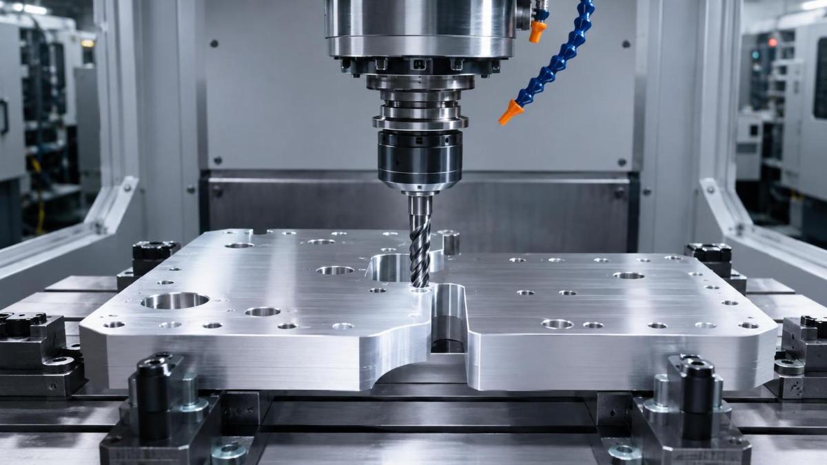
Technical evaluators should assess cutting tools as part of the component-quality system, because tool geometry and condition directly influence the final edge profile.
An edge that appears clean visually may still contain rolled material, microcracks, torn grains, or local deformation that compromises later forming, welding, coating, or sealing operations.
Edge quality requirements vary by application, but critical components often need controlled burr height, consistent chamfers, limited roughness, and no damage within functional contact zones.
For battery enclosures and busbars, uncontrolled burrs can affect insulation placement, electrical spacing, operator safety, and automated assembly reliability during high-volume production.
For PV mounting hardware, inverter housings, and tracker structures, edge defects can weaken protective coatings and increase corrosion risk in humid, saline, or industrial environments.
Transformer laminations and electrical cabinets require particular attention because sharp or irregular edges may damage insulation, create handling hazards, or reduce stacking consistency.
Tooling decisions therefore should not rely only on cycle time or unit cost. They should connect measurable edge outcomes with downstream performance requirements.
A lower-cost tool becomes expensive when it increases deburring labor, creates inspection failures, shortens coating life, or causes intermittent assembly faults after shipment.
The most useful evaluation question is not whether a tool cuts material. It is whether it maintains the required edge condition across its qualified production life.
This perspective shifts procurement discussions from nominal tool specifications toward repeatability, process capability, maintenance intervals, traceability, and documented application evidence.
How Tool Geometry Controls Burr Formation and Edge Shape
Cutting tool geometry determines how material is sheared, displaced, fractured, and released from the workpiece during drilling, milling, turning, punching, or trimming.
Rake angle is especially important because it influences cutting force, chip flow, heat generation, and the likelihood that material bends rather than separates cleanly.
A positive rake angle generally lowers cutting forces in ductile metals, but excessive positive geometry can reduce edge strength and accelerate tool wear.
Negative or neutral rake designs provide stronger cutting edges, often helping with hard materials, interrupted cuts, and rigid setups, although they may increase deformation.
Clearance angle also matters. Insufficient clearance causes rubbing and heat, while excessive clearance weakens the tool edge and can destabilize cutting behavior.
Tool nose radius and edge preparation affect local stress concentration. A properly honed edge may resist chipping, whereas an overly rounded edge can raise burr formation.
For drilled holes, point angle, helix angle, flute design, and margin geometry affect entry burrs, exit burrs, chip evacuation, and hole-edge roundness.
End mills require evaluation beyond diameter and flute count. Variable helix designs, corner radii, and flute geometry can improve stability and reduce edge tearing.
In sheet processing, punch-to-die clearance strongly affects rollover, burnished zone depth, fracture behavior, and the height of the resulting burr on the exit side.
Technical teams should request application-specific edge data because nominal geometry descriptions do not show how a cutting tool behaves in the intended material and machine environment.
Material Compatibility Determines Whether an Edge Is Clean or Damaged
Cutting tools must be matched to material properties, including hardness, ductility, work-hardening tendency, thermal conductivity, coating condition, and inclusion content.
Aluminum alloys used in battery trays, PV frames, and charging equipment can form built-up edge when tool surfaces promote material adhesion.
Built-up edge changes the effective cutting geometry during machining. It often produces smeared surfaces, inconsistent burrs, poor dimensional control, and unstable surface finish.
Sharp polished carbide tools are commonly effective for aluminum, particularly when paired with suitable lubrication, chip evacuation, and cutting parameters.
Stainless steel presents different risks. Its work-hardening behavior can increase cutting forces and wear, producing rough edges when tools dwell or lose sharpness.
For stainless parts in hydrogen systems, outdoor cabinets, or corrosion-resistant fasteners, stable feed engagement is essential to prevent rubbing and localized material hardening.
Copper and copper alloys demand attention in busbars, terminals, and electrical connectors because soft, conductive material can smear or generate problematic burrs.
Composite panels, fiber-reinforced plastics, and coated materials create another challenge. Conventional cutting can cause delamination, fiber pullout, coating lifting, or exposed substrate edges.
When machining coated steel, evaluators should identify whether the operation occurs before or after coating, since tool selection and edge-protection requirements differ substantially.
Material certificates alone are insufficient. Representative trials should include actual heat treatment, surface condition, thickness, clamping method, and production-lot variability.
Coatings and Tool Materials Influence Wear Stability
Tool material and coating affect how long a cutting edge retains its geometry under heat, friction, abrasion, impact, and chemically reactive machining conditions.
High-speed steel remains useful for certain drilling and forming tasks, while carbide usually provides greater stiffness, wear resistance, and high-speed capability.
Carbide performance, however, depends on grade selection. Grain size, cobalt content, toughness, and edge preparation should match the workpiece and cutting interruption level.
Physical vapor deposition coatings can reduce friction and wear, but the coating must suit the material. An unsuitable coating can increase adhesion or cause unstable chip flow.
Aluminum machining often benefits from polished, low-adhesion tool surfaces, whereas steel machining may benefit from coatings designed for hot hardness and oxidation resistance.
For abrasive materials, coating durability and substrate support become critical. Premature coating failure can expose the cutting edge and quickly change burr behavior.
Wear should be evaluated by its effect on edge quality, not only by visible flank wear measurements. Small changes can create unacceptable exit burrs.
Tool-life criteria should include burr height, edge roughness, dimensional drift, surface damage, cutting force, and downstream reject rate at defined inspection intervals.
Many production lines replace cutting tools only after breakage or obvious degradation. This approach allows an extended period of hidden quality deterioration before action occurs.
A better approach establishes a validated replacement threshold based on edge-quality capability, making maintenance predictable and reducing sudden process variation.
Machining Parameters Can Improve or Undermine Tool Performance
Even the best cutting tools cannot deliver consistent edge quality when spindle speed, feed rate, depth of cut, coolant flow, or workholding are poorly controlled.
Feed rate is commonly misunderstood. Reducing feed excessively can cause rubbing rather than cutting, leading to heat buildup, work hardening, and material smearing.
Increasing feed may reduce rubbing, but it can also enlarge exit burrs or overload delicate edges. The optimal setting depends on geometry and material response.
Cutting speed affects thermal conditions and wear mechanisms. Too low a speed can encourage built-up edge, while excessive speed may accelerate thermal wear.
Coolant selection and delivery are equally important. Effective coolant reaches the cutting zone, controls temperature, improves lubrication, and removes chips before recutting occurs.
Air blast or minimum-quantity lubrication may work in some aluminum applications, but complex enclosed features may require through-tool coolant for reliable chip evacuation.
Workholding rigidity directly affects edge consistency. Vibration produces chatter marks, localized tearing, dimensional variation, and unpredictable burr patterns at unsupported areas.
Tool runout deserves close attention, particularly for small-diameter cutters and drills. Runout concentrates load on one edge, causing uneven wear and inconsistent hole quality.
Technical evaluators should review process windows rather than single parameter settings. A robust process maintains compliance across reasonable material, tool, and machine variation.
Documented parameter limits also improve transferability when a component moves between plants, suppliers, machining centers, or production shifts with different operating conditions.
Measure Edge Quality Using Functional Acceptance Criteria
Inspection should translate engineering intent into measurable acceptance criteria. Terms such as clean edge or minimal burr are too subjective for reliable supplier qualification.
Burr height is a basic indicator, but it should be measured at relevant locations, including hole exits, interrupted features, thin sections, corners, and assembly interfaces.
Edge break dimensions should also be specified where needed. A controlled chamfer or radius can remove sharpness without reducing structural section excessively.
Surface roughness near an edge may matter when seals, gaskets, electrical contacts, adhesive bonds, or protective coatings depend on stable local conditions.
Microscopic inspection can reveal cracks, tearing, recast layers, delamination, or coating disruption that standard visual inspection may not detect consistently.
For critical energy equipment, inspection plans should link edge characteristics to risk. A cosmetic panel and a high-voltage conductor should not receive identical scrutiny.
Statistical process control helps evaluators distinguish isolated defects from systematic tool degradation. Trend data is more useful than pass-fail samples alone.
Capability metrics such as Cp and Cpk should be interpreted against meaningful tolerances. A statistically capable process remains valuable only when specifications reflect functional needs.
Supplier audits should verify calibration, sampling frequency, tool-change records, first-off inspection, nonconformance handling, and traceability for high-risk component families.
When evaluating cutting tools, request before-and-after evidence: fresh-tool results, mid-life results, end-of-life results, and results after routine maintenance activities.
A Practical Evaluation Framework for Energy Infrastructure Components
Start by identifying the component's functional edge risks. Consider electrical clearance, insulation protection, corrosion exposure, sealing surfaces, fatigue loading, and automated assembly contact points.
Next, define measurable edge criteria before comparing tools. Include burr direction, maximum height, allowable edge radius, local roughness, visual defects, and inspection method.
Select representative test parts rather than simplified coupons whenever possible. Production components reveal practical effects from geometry, clamping, access limitations, and feature interactions.
Test candidate cutting tools across a planned life cycle. Early samples can conceal problems that emerge after coating wear, chip packing, thermal loading, or gradual runout.
Record machine settings, coolant condition, holder type, runout, material batch, operator shift, and inspection results so findings can be reproduced and defended.
Evaluate downstream performance as part of the trial. Track deburring time, coating adhesion, gasket installation, weld quality, assembly force, and electrical insulation outcomes.
Compare total process cost, including tool price, cycle time, scrap, rework, cleaning, consumables, maintenance, inspection effort, and potential field-quality exposure.
Standardize successful cutting tool combinations in controlled process documentation. Approved geometry, grade, coating, holder, and parameters should not be substituted casually.
For globally sourced infrastructure hardware, align supplier requirements with applicable IEC, UL, IEEE, and internal qualification expectations instead of relying on local workmanship conventions.
Clear specifications allow procurement, manufacturing, quality, and engineering teams to evaluate tooling decisions using shared evidence rather than subjective visual impressions.
Conclusion: Treat Cutting Tools as a Reliability Variable
Cutting tools affect edge quality through geometry, material compatibility, coating behavior, wear resistance, machine parameters, and process stability. Their impact extends beyond machining.
For technical evaluators, the strongest decision is based on functional edge requirements, representative trials, measured tool-life performance, and evidence from downstream manufacturing operations.
A tool that consistently limits burrs, protects surface integrity, and maintains dimensional control can reduce rework while supporting safer, more reliable energy infrastructure hardware.
In high-performance applications, edge quality should be qualified as an engineering characteristic. That makes cutting tool selection a controlled reliability decision, not a purchasing afterthought.