Which hydrogen storage solutions in Europe meet project safety requirements?
auth.Robert GreenTime
Sep 04, 2026Click Count
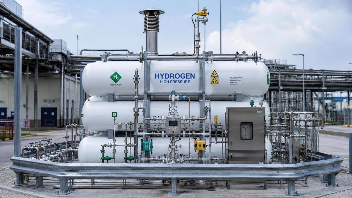
European hydrogen storage projects meet safety requirements when the storage technology, pressure boundary, hazardous-area concept and operating envelope are engineered as one system. A vessel with an appropriate pressure rating is not automatically suitable once it is connected to compressors, valves, pipework, electrical equipment and a site with restricted ventilation. The strongest technical choices are those supported by documented conformity, compatible materials, defined protective functions and a layout that allows leaks to disperse or be detected before an ignitable atmosphere develops.
For most stationary projects, the practical options are compressed gaseous hydrogen, liquid hydrogen, metal-hydride storage and, in more specialised cases, hydrogen stored within a chemical carrier. Each can be acceptable in Europe, but each creates a different safety case. Selection should start with the required delivery pressure, inventory, refill pattern, temperature range, footprint and separation distances. These conditions determine whether compliance with the Pressure Equipment Directive (PED), ATEX requirements, relevant ISO standards and local authority conditions can be demonstrated without extensive redesign.
Compressed gaseous hydrogen: the usual route, with pressure-system obligations
Compressed hydrogen storage is widely used where hydrogen is produced by electrolysis, delivered in tube trailers or consumed by fuel cells, industrial processes or vehicle-fuelling equipment. Storage may use steel cylinders, tube bundles, composite cylinders or larger stationary vessels. The technology is familiar, but the engineering margin is strongly affected by pressure level, cycling duty and connection design.
For fixed installations, PED applicability must be assessed for each pressure-retaining item and assembly rather than assumed from the vessel certificate alone. Vessels, manifolds, filters, separators, flexible connections and safety accessories may fall into different conformity categories. The final assembly also needs a clear definition of its maximum allowable pressure, design temperature, test basis, overpressure protection and inspection arrangement. A component marked for pressure service does not prove that the assembled storage package is compliant at the intended operating conditions.
High-pressure systems demand attention to fatigue. Repeated filling and drawdown create pressure cycles in cylinders, valves, fittings and joints. Composite cylinders require a documented service-life approach that reflects their approved duty, external damage exposure and inspection provisions. Steel vessels have different failure mechanisms, including corrosion at external supports, coating damage and local stress concentration around nozzles. A long storage duration does not remove this issue: low-frequency cycling can still occur during commissioning, balancing, emergency depressurisation and intermittent renewable generation.
Hydrogen-compatible materials are equally important. Hydrogen can affect the ductility and crack-growth behaviour of certain metals, especially where high strength, elevated pressure, low temperature and tensile stress coincide. Material selection must be reviewed alongside welding procedures, heat treatment, hardness controls and the actual gas purity. A specification based only on nominal alloy grade leaves gaps where welds, threaded fittings, sealing faces and heat-affected zones are exposed to the most demanding conditions.
Where gaseous storage layouts fail review
Many design reviews identify the same weak point: the vessel enclosure is considered, while the compressor, vent header and connection points are treated as ancillary equipment. In reality, flanges, instrument connections, valve stems, pressure-relief outlets and trailer-coupling zones often have a higher leakage likelihood than the vessel wall. The hazardous-area classification must cover credible releases from these points, taking account of ventilation direction, roof geometry, cable routes, pits, canopy structures and nearby air intakes.
Outdoor installation usually simplifies dispersion, provided that walls, noise barriers and equipment skids do not create trapped upper volumes. Hydrogen rises rapidly, so an apparently open structure can still retain gas beneath a solid roof, inside a cable tray corridor or above a suspended ceiling. Enclosures need a credible ventilation basis and detection coverage where hydrogen can accumulate, rather than detectors positioned only at convenient access height.

Liquid hydrogen: suitable where density matters, but governed by cryogenic hazards
Liquid hydrogen can reduce storage volume substantially compared with compressed gas, which makes it relevant where a large inventory must fit within a constrained site. Its safety basis is different. The tank, transfer lines and valves operate at cryogenic temperatures, boil-off must be managed, and a release can create both a cold-hazard zone and a flammable vapour cloud after warming and mixing with air.
A liquid-hydrogen installation should be evaluated as a cryogenic process system, not as a larger version of compressed storage. Insulation performance, vacuum-jacket integrity, thermal contraction, low-temperature valve capability and vent routing all affect safe operation. Relief devices must protect credible blocked-in volumes, heat ingress scenarios and abnormal pressure rise while discharging to a location that does not expose occupied areas, fresh-air intakes or equipment that could become an ignition source.
Material compatibility extends beyond hydrogen embrittlement. At cryogenic temperature, common materials can lose toughness, seals can stiffen, and differential contraction can alter preload in bolted joints. Pipe supports must permit movement where required but restrain lines against vibration and accidental impact. A transfer hose or loading arm needs a controlled connection and disconnection sequence, breakaway protection where vehicle movement is credible, and a defined response to loss of vacuum or abnormal boil-off.
Local permitting authorities may focus closely on inventory, setback distances, tanker access, drainage paths and emergency services access. The site plan therefore needs to be mature before the storage equipment is fully fixed. Moving a vent stack, tank orientation or unloading point late in the project can affect classified areas, civil works, electrical routing and fire strategy at the same time.
Lower-pressure alternatives require a different safety argument
Metal-hydride systems retain hydrogen within a solid material and can operate at pressures below conventional high-pressure cylinder storage. This can reduce stored-gas pressure, but it does not eliminate hazards. Heat is released during charging and required during discharge, so thermal management governs both availability and safety. A blocked cooling circuit can slow absorption or raise temperatures; insufficient heat during discharge can reduce hydrogen flow when it is needed. The system should include temperature monitoring, pressure protection and controls that address credible thermal excursions.
These systems are often considered where compact, lower-pressure storage is preferred and the duty profile permits slower charge or discharge behaviour. Their suitability should be judged from actual thermal cycling, maintenance access, containment integrity and end-of-life handling rather than pressure alone. A low-pressure vessel with a poorly controlled heat source, inadequate gas detection or inaccessible isolation points does not provide a stronger project safety position.
Hydrogen carriers such as ammonia or liquid organic hydrogen carriers shift some risks away from free hydrogen storage but introduce separate chemical, thermal and process hazards. They are not interchangeable with direct hydrogen storage. A project using a carrier needs a safety basis for the carrier itself, the conversion equipment, impurities, vents, drainage and potential release products. Treating the carrier package as an upstream supply detail can leave the receiving facility under-designed.
ATEX must be tied to release sources and equipment selection
ATEX compliance is often reduced to purchasing suitably marked electrical equipment. That is incomplete. The starting point is a documented explosion-protection concept that identifies potential release grades, expected ventilation, hazardous-zone extent and ignition sources. Electrical equipment selection follows from this classification, but so do decisions about motors, instrument enclosures, hot surfaces, static electricity, maintenance tools, vehicle access and lightning protection.
Hydrogen has a broad flammability range and low ignition energy, so small releases around high-pressure connections deserve careful treatment. Ventilation fans, where used, must be appropriate for their installed zone and arranged so that failure does not create an unrecognised accumulation condition. Gas detectors should not be treated as a substitute for ventilation or sound mechanical design. Detection supports prompt isolation, alarms and emergency actions; it does not make a persistent leak acceptable.
The cause-and-effect logic should state what each detector signal does. Typical functions may include local alarm, compressor shutdown, closure of automated isolation valves, ventilation response, process depressurisation where justified, and transmission to the site control system. These actions need proof testing and a manual reset philosophy that avoids automatic restart after a gas alarm. Detection locations also require maintainable access, calibration arrangements and protection from weather or process conditions that could impair response.
Fire protection is primarily about isolation, dispersion and exposure control
Hydrogen flames can be difficult to see in some conditions, and jet releases can generate high local thermal loads. Fire strategy should therefore establish how the inventory is isolated, whether controlled depressurisation is required, how adjacent equipment is protected from radiant heat, and where emergency responders can approach safely. Water may be relevant for cooling exposed equipment, but it is not a universal response to a hydrogen release. The design should avoid relying on a single intervention after a loss of containment.
Passive measures include separation distances, blast-resistant or directing barriers where supported by the hazard study, impact protection, non-combustible construction near storage, clear emergency access and routing of vents away from congested areas. Active measures include detection, emergency shutdown, fire detection where appropriate and remotely operable isolation. Their effectiveness depends on the response sequence: closing a valve that traps gas in an overheated segment can create a new pressure hazard unless relief protection and isolation boundaries have been reviewed together.
Documentation must connect equipment certificates to the installed facility
A defensible handover file links the design basis to the physical installation. It should include pressure-system documentation, declarations and certificates applicable to supplied equipment, hazardous-area drawings, loop diagrams, relief-device data, material records where required, weld and test records, operating limits, inspection requirements and commissioning evidence. For imported skids, document review should establish whether conformity assessment covers the delivered assembly, its intended configuration and the jurisdiction where it will be installed.
Factory acceptance testing does not replace site acceptance. Transport restraints may be removed, tubing can be disturbed, vent pipes can be altered, electrical segregation may change, and civil interfaces may differ from the approved layout. Site testing should verify leak tightness using an approved method, functional operation of alarms and shutdowns, valve fail positions, detector response, vent-path completion, bonding and earthing continuity, and labelling of isolation points. Pressure testing must follow the approved procedure; improvised testing with hydrogen is not an acceptable commissioning shortcut.
Selection criteria that prevent late-stage redesign
The appropriate European hydrogen storage solution is therefore the one whose certificates, materials, layout and operating logic remain consistent after site-specific hazards are applied. Compressed gaseous storage is often the most direct choice for modular stationary systems; liquid hydrogen becomes relevant when density and logistics justify cryogenic complexity; metal hydrides fit narrower thermal-duty applications. None should proceed on equipment documentation alone. The installation must show that pressure control, explosive-atmosphere protection, leak response and emergency isolation work together under normal operation, foreseeable faults and maintenance conditions.
Recommended News
- 00
0000-00
What to verify before choosing a hydrogen storage tank supplierHydrogen storage tank supplier checklist: verify pressure ratings, certifications, traceability, safety controls, delivery capability, and lifecycle value before you buy. - 00
0000-00
Which hydrogen storage solutions in Europe meet project safety requirements?Hydrogen storage solutions Europe: compare safe compressed, liquid and metal-hydride options with PED, ATEX and site-design guidance for compliant projects. - 00
0000-00
How global trade shifts are changing hydrogen storage project costsGlobal trade is reshaping hydrogen storage project costs through tariffs, sourcing risks, logistics delays, and compliance pressures. See what drives budget overruns.
000000-00
{item.title}{item.description}Search News
Industry Portal
Hot Articles
- What determines the solar tracker price for utility-scale projects?Solar tracker price for utility-scale projects depends on steel, site conditions, controls, logistics, installation, and lifecycle value. Learn how to compare proposals wisely.
- Which machinery parts wear fastest in solar tracker drive systems?Machinery parts in solar tracker drive systems wear fastest at slew drives, bearings, motors, and couplings. Discover warning signs and maintenance tips.
- How grid monitoring systems improve outage response in the Middle EastDiscover how grid monitoring systems Middle East utilities use to locate faults faster, prioritize critical loads, and improve outage response across complex power networks.
Popular Tags